Abstract
Background The current generation of total disc replacements achieves excellent short- and medium-term results by focusing on restoring the quantity of motion. Recent studies indicate that additional concerns (helical axes of motion, segmental torque-rotation behavior) may have important implications in the health of adjacent segments as well as the health of the surrounding tissue of the operative level. The objective of this article is to outline the development, validation, and biomechanical performance of a novel, compliant-mechanism total disc replacement that addresses these concerns by including them as essential design criteria.
Methods Compliant-mechanism design techniques were used to design a total disc replacement capable of replicating the moment-rotation response and the location and path of the helical axis of motion. A prototype was evaluated with the use of bench-top testing and single-level cadaveric experiments in flexion-extension, lateral bending, and axial torsion.
Results Bench-top testing confirmed that the moment-rotation response of the disc replacement matched the intended design behavior. Cadaveric testing confirmed that the moment-rotation and displacement response of the implanted segment mimicked those of the healthy spinal segment.
Conclusions Incorporation of segmental quality of motion into the foundational stages of the design process resulted in a total disc replacement design that provides torque-rotation and helical axis–of–motion characteristics to the adjacent segments and the operative-level facets that are similar to those observed in healthy spinal segments.
Current total disc replacement (TDR) technologies represent a step forward in addressing the biomechanics of chronic, disc-centric low-back pain. Short- and medium-term results for initial devices have generally been favorable,1–3 although there have been several studies indicating that long-term complications may be of concern.4, 5 None-theless, these devices have introduced a new paradigm of motion preservation that is generally accepted as the path forward for treatment of this extremely debilitating condition. A review of the contributions of these current-generation devices was recently published in the International Journal of Spine Surgery (formerly the SAS Journal).6
Accurate duplication of spinal biomechanics by a TDR relies on mimicking the range of segmental motion, the helical axes of motion (HAMs), and the torque-rotation behavior of the segment (kinetics). Collectively, these qualities will be referred to, in this article, as segmental quality of motion (QOM).7–10 The current generation of sliding–bearing surface disc replacements cannot provide for the same intrinsic QOM and energy storage that the natural intervertebral disc provides. The motion-producing mechanism of most current disc replacements is essentially a ball joint,6 similar in function to successful orthopedic devices developed for application in diarthrodial joints, such as the knee and the hip. As a result, current disc replacements must rely on the surrounding soft tissue or include additional elastic elements, such as springs, to provide QOM. Discs that rely on the surrounding tissue often exhibit a stick-slip movement10 that imposes additional loads on the facets11 and surrounding segments and may lead to accelerated degeneration,12 whereas discs that rely on additional elements, such as springs, may become overly complex.
The motivation for this work stemmed from the observation that achievement of a natural QOM may be simplified through the use of compliant mechanisms. Compliant mechanisms are devices that receive motion through the deflection of 1 or more members.13 By combining structural and elastic elements, compliant mechanisms have shown several advantages over traditional rigid- body mechanisms. These advantages include a reduced number of parts,14 resistance to harsh or corrosive environments,13 higher precision,15–17 wear-free motion,13, 18–20 ease of miniaturization,21, 22 and tailorable force-deflection responses and axes of rotations.13
Because of the possible significant effects that biomechanics may have on long-term outcomes, it has been proposed that QOM considerations should be incorporated into the design phase of the implant.23 Although the exact nature of the appropriate QOM profile is unknown, it is likely that these design considerations should include the proper moment-rotation response (Fig. 1A) and proper HAMs (Fig. 1B). It is also important to consider implant durability (eg, wear, fatigue, and creep) and surgical robustness in the early stages of design. As a result of these requirements and the advantages of compliant mechanisms, compliant mechanisms may offer appealing characteristics when applied to the design and development of TDRs.
(A) Median moment-rotation response and (B) HAM of lumbar spine in flexion-extension. The HAMs of motion in B are represented by lines, the shading of which corresponds to the angular response in A.
This work outlines the development, validation, and testing of a compliant mechanism–based TDR developed at our university (Fig. 2), which was designed to specifically match the segmental biomechanics of the healthy lumbar spine. The primary hypothesis of this study is that the biomechanical (kinematic and kinetic) behavior of the implanted spine could be designed and predicted before cadaveric implantation using traditional design methods coupled with biomechanical analysis techniques. This behavior should be demonstrated through bench-top and cadaveric testing. The described device is currently being prepared for CE mark approval, and clinical testing is anticipated to begin in 2012.
Prototype TDR.
Methods
A 3-step process was used for the design and testing of the implant: (1) a specific QOM profile was selected and designated as the target functional specification, (2) non-linear optimization was used to determine the geometry and mechanical response of the implant and to match the selected QOM profile, and (3) bench-top and cadaveric testing was used to verify the QOM performance of the implant.
Device design
A description of the mathematical modeling of the device is given elsewhere,24 but a brief description of the device is given here for completeness. The device, shown with idealized geometry in Fig. 3, consists of multiple flexures (A–F in Fig. 3), a mobile center, and superior and inferior endplates. Motion in the device is generated through elastic deformation of the flexures (Fig. 3), making it a compliant mechanism. As the device is displaced, the flexures are transferred from 1 surface to another, creating a rolling motion.25, 26 Because the mechanism rolls without slip, wear is not generated from articulating surfaces. Figure 3 shows generic geometry with a constant radius, but the quality and quantity of motion of the mechanism may be modified by changing the geometry of the mobile center and flexures.27, 28
The implant motion profile as viewed from an isometric view (top) and sagittal view (bottom) for an idealized geometry. 6 flexures (A-F) guide the motion of the device while providing a torque-rotation response that mimics that of the intact functional spinal unit.
The quantity of motion (θ) that the device is capable of providing is related to the arc lengths (Li) and radii of the surface (Ri), or 1
1
Because of the rolling nature of the device, the location of the HAM in uniaxial motion lies along the neutral axis of the flexures. By making modifications to the geometry of the surface, the location and path of the HAM can be tailored to mimic that of the healthy spinal segment.24 The momentrotation (M) response of a single flexure of the device may be determined by the Bernoulli-Euler equation as 2
2
where R u (θ) is the radius of the upper contact surface, R l (θ) is the radius of the lower contact surface, and R o (θ) is the radius of curvature of the flexure. It is important to note that the radii are permitted to vary according to the displacement (θ).
The stress within the flexures is dependent on the motion of the device in the primary axis (α) and secondary axis (β), as well as forces exerted on the device (eg, for lateral bending, the primary and secondary axes of motion are the anterior-posterior and medial-lateral axes, respectively), and is 3
3
 4
4
where E is the modulus of elasticity of the material, F c is the axial compressive force, A is the cross-sectional area of the flexure, h is the thickness of the flexure, and w is the flexure width.
A nonlinear optimization routine was used to match a specific QOM profile. The target QOM profile was created from the median moment-rotation response of 10 available profiles from 6 male and 4 female donors ranging in age from 36 to 77 years (mean age, 57 ± 14.8 years). Because of the large stochastic errors related to the measurement of the finite HAM,29 the location and path of the HAMs were selected such that the HAMs were consistent with those reported previously.29, 30
Once the specific target QOM profile was selected, a numerical model was combined with nonlinear optimization to design a device that matched the profile. Mathematical models were used to determine the stress, HAM, and force-rotation response of the device.13, 27 A nonlinear gradient-based optimization routine was used to optimize for the correct surface and flexure geometry that related to the desired performance. The optimization routine was constrained such that the device would (1) have an infinite fatigue life under coupled loading conditions of ± 10 Nm in flexion-extension, lateral bending, and axial rotation; (2) fit in an implant space with dimensions no greater than 22 mm, 36 mm, and 12 mm in the anterior-posterior, left-right, and superior-inferior directions, respectively; and (3) match the selected QOM profile in flexion-extension and lateral bending. After the optimization routine converged, the von Mises stress was calculated through finite element modeling (ANSYS V10, ANSYS, Inc., Canonsburg, Pennsylvania) and used to verify that the device would have an infinite fatigue life under the additional loading conditions of ± 10 Nm in flexion-extension, lateral bending, and axial rotation.
Isolated implant testing
The force-rotation response of the implant was initially verified through a “modified F1717” compression bending test in flexion-extension and lateral bending.31 The prototype was placed between 2 ultrahigh-molecular-weight polyethylene (UHMWPE) blocks fixed to a tensile/compressive tester through pinned connections. The implant was oriented to place the center of pressure (COP) 4 mm from the anterior endplate edge (Fig. 4). The UHMWPE blocks were then compressed axially, and the angle of rotation was determined through optical markers located on the UHMWPE blocks and a stereoscopic camera system.32 These results were compared with the values predicted during the design phase.
(A) Functional schematic of modified F1717, with center of pressure illustrated by dashed line, and (B) actual test setup.
The use of the modified F1717 test was chosen above other testing procedures (ie, modified F2423 or modified F2346) because of its simplicity, adaptability, and ability to be performed without highly specialized test equipment. However, the test does have several limitations. First, the location of the COP must be located within the endplate of the test specimen to prevent separation of the test specimen from the UHMWPE blocks. The location of the COP with respect to the Instantaneous Axis of Rotation (IAR) means that a large shear force must be exerted on the test specimen to provide a significant amount of rotation. Second, the fixturing of the test specimen prohibits the use of a compressive load that passes through the center of rotation of the natural intervertebral disc.33 However, given that the intent of the bench-top testing was to validate a more comprehensive analytic model, the described testing provided a direct way to evaluate the accuracy of the models in a nontrivial loading condition with clinical applicability.
Integrated implant testing setup
In addition to the modified F1717 discussed earlier, additional single-level “pure-moment” cadaveric tests were used to verify that the designed-for implant behaved as expected in vitro. A cadaveric fresh-frozen lumbar spine specimen (L3-4, female cadaver, aged 65 years) was acquired from an accredited tissue bank under the approval of an internal review board. The specimen was carefully dissected to preserve the ligaments and disc. The superior and inferior vertebral bodies were potted into polyester resin, and optical markers were attached to facilitate motion tracking during testing.
Flexibility testing of the specimen was performed using the custom spine tester shown in Fig. 5. The spine tester design was based on the work of Goertzen et al.34 but was modified to include an integrated environmental chamber, as well as allow for application of a compressive follower load. A pure moment load was applied using a stepper motor. The motor was micro-stepped to a step resolution of 0.09° per step and coupled to the superior potting fixture through 2 universal joints and a ball spline (located to the left in Fig. 6). Labview (National Instruments, Austin, Texas) was used for both data acquisition and control. This configuration allows the specimen to be driven in 1 axis of motion while permitting coupled motions (lateral bending, axial rotation, xyz translation). The specimen was then rotated 90° and tested in lateral bending. Axial rotation was tested by moving the motor to the top of the machine.34 All axes of motion were tested at a rate of 1°/s to a maximum applied moment of ± 9 Nm under a compressive follower load35 of 440 N. The follower load was applied through eyelets attached to the upper potting fixture and the line of action through the Functional Spinal Unit (FSU) axis of rotation. Load positioning was iteratively adjusted by measuring the difference in starting torque with and without the follower load and constraining this value to ± 0.3 Nm. The FSU was preconditioned for a minimum of 20 cycles, until a repeatable torque-rotation response was achieved. An environmental chamber permitted the specimen to be tested at 37°C and greater than 95% humidity. Camera calibration was performed within the chamber to account for optical aberration from the environmental chamber. Rotation of the vertebral bodies was determined through optical markers.32 A kinematic assessment of the implanted and intact FSU was performed by plotting the x-y position of a marker located superior to the right transverse process. No post-processing was used.
Spine tester and environmental chamber.
Resultant prototype surface geometry without flexures or endplates, in the (A) sagittal and (B) frontal planes. (C) An isometric view of the prototype surface and flexure geometry without endplates. A photograph of the prototype with endplates is shown in Fig. 2.
Results
Device design
The method yielded an implant that was within the constrained design space. Namely, the theoretic QOM profile in flexionextension and lateral bending matched the designed-for QOM profile, with kinematic (location and path of HAM) and kinetic (moment-rotation) error of 0.0% in flexion-extension and lateral bending. The von Mises mean and alternating stress of the device predicts, with a factor of safety greater than 1.2, that the design is capable of an infinite fatigue life under coupled loading conditions of ± 10 Nm applied around all axes of rotation. The resulting prototype device, including endplates, measures 21.6 mm, 36 mm, and 11 mm in the anterior-posterior, left-right, and superior-inferior directions, respectively, and is shown in Figs. 2 and 6.
Isolated implant testing
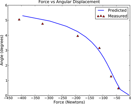
The isolated testing showed that the device demonstrates a nonlinear stiffness throughout the motion of the device, as shown in Fig. 7. The maximum angular error occurred in flexion and was 0.3°, also shown in Fig. 7.
Force-rotation response in isolated testing conditions as compared with predicted values.
Integrated implant testing
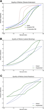
The range of motion of the integrated FSU (intact FSU) were 8.6° (9.3°) of flexion, 4.3° (3.3°) of extension, 3.75° (4°) of left lateral bending, 7.8° (5°) of right lateral bending, 2° (2.75°) of right axial rotation, and 1.75° (3.25°) of left axial rotation. The moment-rotation response of the implant, when integrated into the FSU, and the moment-rotation response of the intact FSU in flexion, extension, and left lateral bending are shown in Figs. 8A and 8B. Flexion-extension results (Fig. 8A) include comparison data from a first-generation mobile core TDR implant.10
Moment-rotation response of FSU before and after implantation, shown in (A) flexion-extension, (B) lateral bending, and (C) axial rotation. (A) Published flexion-extension QOM data for a first-generation “slidingfriction” TDR are included for comparison.
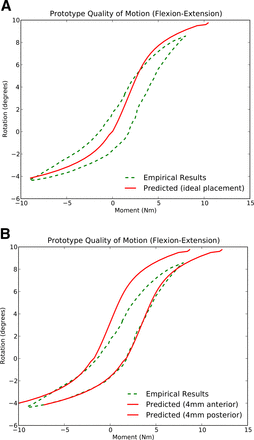
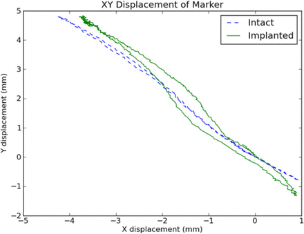
The moment-rotation response in flexion-extension was compared with the designed-for case and is shown in Fig. 9A. The consequences of nonideal surgical misplacement on the moment-rotation response of the implant by ± 4 mm were also calculated and are shown in Fig. 9B. In addition, the x,y,z displacement of a marker located superior to the right transverse process of the superior vertebra was monitored for both the intact and implanted case. The greatest error in x-y marker position occurred at full extension and was 0.45 mm. The path of the marker for the intact and implanted conditions in flexion-extension is shown in Fig. 10.
Measured response of integrated FSU and (A) predicted QOM when placed in its proper location and (B) predicted QOM when misplaced by ± 4 mm to its ideal location.
Measured displacement of a marker mounted on the superior vertebra of the FSU before and after implantation shown in flexion-extension.
Discussion
The described disc replacement device shows 2 characteristics that may provide significant advantages over first-generation lumbar TDRs: healthy segmental QOM and decreased wear potential.
The torque-rotation behavior, as evidenced by the minimal changes in angular displacement (Fig. 8), and HAM location, as evidenced by the small (0.45-mm maximum error) change in marker displacement (Fig. 10), mimic those of a healthy spinal segment. Whereas the current generation of TDRs produces hypermobility for some movements and hypomobility for others36 and large errors in angular displacement when compared with their intact cases (4.1°),10 the implant under consideration produced consistent motion patterns. Because both hypermobility and hypomobility have been attributed to the degeneration of the spine,37 consistent motion patterns become crucial for the long-term maintenance of spinal health.
As shown in Fig. 8, the moment-rotation of the implanted and intact FSUs in flexion-extension and right lateral bending was within 1.4° for flexion-extension and 0.25° for right lateral bending. The deviation for left lateral bending, shown in Fig. 8B, can be attributed to elastic deformation of the artificial endplate. This deviation was caused by a Y-shaped endplate design that resulted in the left side of the endplate being substantially less stiff than the right side. The Y-shaped endplate was not explicitly included into the design process. The endplate design has since been modified to be symmetric about the sagittal plane.
Segmental torque-rotation and range-of-motion results do not completely represent the kinematic behavior of the lumbar spine. The location of the finite HAMs, combined with geometric parameters of the device, provides a complete description of the segmental motion, including vertebral displacements.29 In the present case, the HAMs for the device were designed based on reported measurements from the literature.29 The agreement between the displacement paths of an identically placed point on the superior vertebra as shown in Fig. 10 provides validation that the location and path of the finite HAMs of the implanted condition match those of the intact FSU.
The second potential advantage of the device (decreased wear potential) stems from its compliant-mechanism design but was not specifically tested in this study. Because the compliant-mechanism design of the device dictates rolling motion of the mating surfaces with no sliding, the wear potential is dramatically reduced. This quality is clinically relevant for all arthroplasty devices including TDRs.18–20 However, manufacturing tolerancing, nonphysiologic shear loading, and choice of implant material could challenge the practical implementation of a truly “zero-wear” device. Additional testing is needed to confirm the wear characteristics of the implant.
Perhaps of most importance, the QOM of the implant as measured through bench-top (modified F1717) and in vitro testing was achieved directly through the design process. The ability to predict and design for specific QOM profiles before cadaveric testing allows for rapid design iterations, as well as predictable biomechanics. This process opens the door to future possibilities for patient-, gender-, or age-specific implants. Specific implants for specific QOM profiles would allow for the large variation in QOM profiles across the degenerative cascade.9 However, the clinical relevance of such a task, as well as the practicality, remains uncertain. Additional research is needed to determine the need and appropriate design parameters (eg, size, angulation, QOM profile, and variations of QOM profile due to surgical approach) to account for these changes.
Compliant mechanism–based design is not without its own set of challenges. One of the greatest challenges is that compliant mechanisms provide motion through deflection, which couples motion with stress. Careful consideration must be given to the selection of both material and design characteristics to prevent fatigue failure. This selection criterion can make the design process much more difficult than traditional rigid-body mechanics because one must also account for coupled motions that produce biaxial or triaxial stress states. Fortunately, there exists a wide range of materials (such as titanium, polyetheretherketone, and silicone) that exhibit properties that make them well suited for bio-logically compatible compliant mechanisms. Some (eg, titanium) exhibit well-known fatigue and creep characteristics that, when used with compliant-mechanism design techniques,13 can provide for an implant capable of an infinite fatigue life such as the implant studied in this study. The compliant nature of the implant also indicates the potential for elimination of the motion that induces wear.
Conclusion
Incorporation of compliant-mechanism design theory into the foundational stages of the design process resulted in a TDR design that restored quantity (range) of motion in flexion-extension and lateral bending. In addition, the QOM, when implanted into the FSU, approximated that of the intact control. Furthermore, bench-top stiffness testing showed that the QOM was generated through elastic deformation and that the implant performed as designed. Given the compliant nature of the implant, motion-induced wear is not anticipated. As a result of the close approximation of the implant to the intact condition, one would expect minimal changes to the biomechanics of the segments adjacent to the operative segment. In summary, the device studied provides a new alternative for the treatment of chronic, disc-centric low-back pain, one that was designed from its initial conception to duplicate the QOM of the healthy spinal segment and invites further investigation.
- © 2012 ISASS - International Society for the Advancement of Spine Surgery. Published by Elsevier Inc. All rights reserved.
This is an Open Access article distributed under the terms of the Creative Commons Attribution-Noncommercial 3.0 Unported License, permitting all non-commercial use, distribution, and reproduction in any medium, provided the original work is properly cited.

