Abstract
Background Many decompression procedures involve complete or partial facetectomy. Spinal fusion usually stabilizes the motion segment after complete facetectomies. However, problems with fusion, such as adjacent-level degeneration, have increased interest in motion- preservation technologies. Facet arthroplasty may become an important posterior motion-preservation device, but its biomechanical literature is sparse.
Methods We conducted an in vitro investigation and finite element study to compare the biomechanical effects of an artificial facet system to the intact spine. In the in vitro study, we tested human osteo-ligamentous segments (L3-S1) in intact, injured, and artificial facet–repaired conditions. For the finite element study, we used a 3-dimensional ligamentous L3-S1 segment model. We simulated destabilization in the intact model by removing the facets across the L4-L5 functional unit, then repaired it with appropriately sized facet implants and compared the ranges of motion, facet loads, disc pressures, and device loads. We also analyzed a finite element model with a rigid posterior pedicle-rod fixation system. We subjected the cadaveric specimens and the models to 400 N of follower load plus a 10 Nm moment in extension, flexion, bending, and rotation. We used a novel technique to apply the follower load in the finite element models such that preload induced minimal vertebral rotation during the range of motion.
Results The predicted ranges of motion for the intact and implanted models were consistent with cadaver data. After destabilization and facet replacement, the artificial facet system restored motion in all loading modes to intact values. The implant facet loads were similar to intact facet loads in extension and axial rotation, but less in lateral bending. The intradiscal pressure at the implanted level for the facet replacement device was similar to the intact pressure, whereas with the rigid system the intradiscal pressure was up to 70% less than the intact pressure. The maximum von-Mises stress predicted in the facet replacement construct was 85 MPa in extension at the bone–pedicle screw interface, compared with 174 MPa in the rigid system. Contact stresses at implant mating surfaces were minimal.
Conclusions The artificial facet system replicated natural facet kinematics. The cadaveric ranges of motion and the predicted finite element–based data indicated that the implant can “restore” the normal function of the segment after artificial facet replacement.
Clinical Relevance Compared to rigid posterior pedicle-rod fixation, the artificial facet system restored the intact mechanics at the implanted level and may prevent adjacent-level degeneration.
INTRODUCTION
Facet degeneration can lead to several spinal disorders that result in low-back and leg pain. When conservative care such as medication and exercise fails to relieve pain, surgical intervention is considered. In cases such as severe facet tropism, facet hypertrophy, arthritic or degenerated facet joints, and spinal stenosis, partial or full laminectomy with facetectomy surgeries may be warranted to relieve patients of low-back and leg pain. However, these decompression procedures may lead to spinal instability.1–5 Traditionally, spinal arthrodesis—or, as it is commonly called, fusion—has been the treatment option surgeons use to provide stability to the spine after decompression. However, the recognition of adjacent-level disease as a condition linked to fusion6 has spawned an interest in the evaluation of motion-preservation devices as alternatives. The premise of facet joint replacement technology is that the devices will help restore normal spinal motion at the involved levels.
Joint replacement systems for the knee and hip have a long history of clinical success with implants designed to mimic the normal healthy anatomy.7, 8 These systems also contain instrumentation to precisely and reproducibly place the implants. A deep understanding of the morphology of the facet joint in relation to its biomechanical function is crucial to the development of a facet arthroplasty device. This concept implies that one needs to investigate the biomechanics of the segment after artificial facet placement with the hypothesis that the changes in various parameters compared to the intact segment are minimal. We undertook a 2-part investigation. A well-established in vitro cadaver protocol was used for kinematics. An experimentally validated finite element model was used for the quantification of facet loads, intradiscal pressures, and stresses in various components of the facet replacement system and also in a model stabilized with a pedicle-screw rigid-rod fixation system.
The artificial facet system used for the study was the Anatomic Facet Replacement System (AFRS) (Facet Solutions Inc, Logan, Utah). The system attempts to address posterior lumbar spine pathologies while preserving stability and natural biomechanics. It would thereby mitigate any potential adjacent-level effects that result from the reduction or elimination of motion as seen in semiconstrained dynamic stabilization and fusion devices.9
The AFRS consists of a precision instrumentation set and an anatomic facet implant family whose design is based upon a comprehensive computed tomographic morphology study of the facet joint.10 The system utilizes traditional pedicle screw fixation of its superior and inferior facet implants (Figure 1). The alignment of the implants to the patient's anatomic planes is very precisely controlled by the instrumentation. However, each implant has a polyaxial junction that accommodates ±15° of variability in pedicle screw placement. The left and right cephalad facet implants are connected by a cross-linking member, which provides additional stability to the construct. The facet implants are manufactured from a wear-resistant alloy, cobalt-chromium- molybdenum. This material has a long and successful history of clinical use in other metal-on-metal total joint replacement systems.11, 12 Pedicle screws are manufactured of titanium alloy. Titanium plasma spray and hydr oxyapatite coatings are applied to the bone interface surfaces of the facet implants.
Anatomic Facet Replacement System (Facet Solutions Inc, Logan, Utah) placement shown on a Sawbones spine model (Pacific Research Laboratories Inc, Vashon, Wash). The system was used for simulation in the finite element model and cadaver tests.
MATERIALS AND METHODS
Finite Element Analysis
Finite Element Model of the Ligamentous L3-S1 Segment
The lumbar spine finite element model used in this investigation consisted of a 3-dimensional mesh of L3-S1 ligamentous spinal segment and is an extension of the models previously developed in our laboratory. 13–16 Details of model formulation and validation are reported elsewhere.13–16
Intact L3-S1 Finite Element Model
The intact L3-S1 finite element model included 31,054 elements and 38,664 nodes (Figures 2a and 2b). Material properties of the various tissues (Table 1) were selected from the literature, including our own experimental data.13–16 The apophyseal (facet) joints were simulated with 3-dimensional gap contact elements. These elements transferred force between nodes along a single direction as a specified gap between these nodes closed. The cartilaginous layer between the facet surfaces was simulated using the ABAQUS/Standard version 6.5 (ABAQUS Inc, Providence, RI) “softened contact” parameter, which exponentially adjusted force transfer across the joint, depending on the size of the gap. An initial gap of 0.5 mm was specified as reported for cadaveric specimens. At full closure, the joint assumed the same stiffness as the surrounding bone. The ligaments were simulated as nonlinear tension-only members. The disc annulus was represented as a composite of fibers embedded in the ground substance and the disc nucleus as “incompressible” fluid encased within the annulus.
Three-dimensional finite element model of the ligamentous L3-S1 segment: (a) intact model, (b) mid-sagittal cross-section of the model showing important anatomical features.
Artificial Facet Implanted Model
The intact model was modified to simulate destabilization by removing the facets across the L4-L5 function unit. The geometry of the artificial facet system was imported into ABAQUS/Standard and meshed. All implant components were assigned as cobalt-chromium-molybdenum (Young modulus, E = 241 GPa; Poisson ratio, v = 0.3), except the titanium alloy screws (Young modulus, E = 115 GPa; Poisson ratio, v = 0.3). The articulating surfaces of superior and inferior facets of the device were connected to pedicle screws, 6.5 mm in diameter and 35 mm long by connecting shafts (Figures 3a and 3b). The cephalad facets on the 2 sides were also connected to each other by means of another horizontal connecting shaft. The pedicle screws were tied to the holes in the pedicle bone, thereby simulating perfect bone ingrowth. Contacts were defined between the articulating faces of the superior and inferior facets with contact elements from ABAQUS.
Finite element model of the injured spine repaired with the Anatomic Facet Replacement System: (a) posterior view, (b) side view. A small hole was made in the interspinous ligament to place the transverse rod across the two facets.
Rigid Posterior Pedicle-Rod Fixation Model
To simulate a pedicle screw–based rigid-rod implant, cylindrical rods of uniform cross section were tied to the superior and inferior pedicle screws, bilaterally (Figures 4a and 4b). The pedicle screws were tied to the holes in the pedicle bone, thereby simulating perfect bone ingrowth. The titanium screws were 6.0 mm in diameter.
Finite element model simulating pedicle screw–based rigid rod implant: (a) rear view, (b) side view.
Boundary and Loading Conditions
The inferiormost surface of S1 was constrained in all 3 directions. A novel technique was used to apply 400 N follower load such that its application did not induce any rotation in the vertebrae. Springs were bilaterally attached across each motion segment and iteratively positioned such that load in the spring did not induce any relative rotational motion across the motion segment. The spring on each side was given a pre-tension of 200 N and spring stiffness was defined as zero. The zero spring constant ensured that deflection in the spring did not affect the pre-tension and, thus, it acted as a rope with constant tension of 200 N on either side. Moment load of 10 Nm was applied in the intact, injured, and implanted models at the superior L3 endplate in flexion, extension, bending, and axial rotation.
In Vitro Testing
Specimen Preparation
Fresh ligamentous human lumbar spine specimens (L3-S1) were procured and stored in double plastic bags (Hefty One Zip; Pactiv Corp, Lake Forest, Ill) at –20 °C. For each specimen, anteroposterior and lateral radiographs were obtained and 6 specimens with good bony and ligamentous integrity were selected for the study. Before testing, the specimens were thawed to room temperature for 10 hours and then cleaned to remove any extraneous fat, muscle, and tissue. The L3 and S1 vertebrae of each specimen were then potted firmly in a mixture of Bondo auto body filler (Bondo MarHyde Corp, Atlanta, Ga) and fiberglass resin (Home-Solution All Purpose; Bondo Marhyde). A loading frame was attached to the L3 vertebra before potting. L-shaped Plexiglas markers (Northern Digital Inc, Waterloo, Ontario), each having 3 infrared light–emitting diodes, were secured rigidly to each vertebral body to track its motion with the Optotrak 3020 motion analysis system (Northern Digital Inc). One of the Plexiglas markers was fixed to the base and acted as the reference frame. This specimen preparation procedure was similar to those described in the literature, including our own publications.3, 17, 18
Testing Protocol
The prepared specimen was mounted on the testing rig and 400 N of follower load was applied to the specimen by means of cable-and-pulley arrangement (Figure 5). Pure moments of 10 Nm in steps of 2.5 Nm in flexion, extension, bending, and rotation were applied to the specimen by hanging weights to the loading frame. Specimen was sprayed with saline solution once every 30 minutes to prevent drying. After each load step, the spatial data of the infrared light–emitting diodes were acquired with the Optotrak system. From these data, the angular motion of each vertebra was calculated according to the principles of rigid body motion.
Potted specimen under testing showing LEDS and pulleys for applying follower load.
Following the testing and data acquisition of the intact motion segment, a neural decompression was simulated by performing only a complete bilateral facetectomy. The ligaments that ran between the spinous processes and lamina of adjacent levels (interspinous, supraspinous, and ligamentum flavum) were left intact. A set of precision instrumentation was then used to prepare bone beds for each of the 4 facet implants. The pedicles were tapped and appropriately sized pedicle screws implanted. Much as in a total hip or knee surgery, a set of trials identical in geometry to the facet implant family was utilized to determine the optimal sizes. The final implants were secured to the bone bed and a cross-linking bar was attached, connecting the cephalad pair of facet implants through a small hole in the interspinous ligament (Figure 6). Motion data were acquired for the destabilized artificial facet system–repaired specimens under the same loading conditions as with the intact specimen. The data were analyzed with 2-tailed paired t tests to determine statistical significance between intact, injured, and repaired specimens.
In vitro testing of Anatomic Facet Replacement System–repaired spine segment. The supraspinous ligament and majority of the interspinous ligament were left intact.
RESULTS
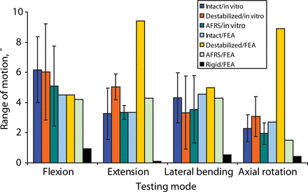
The cadaveric study showed that the artificial facet system was able to restore the motion to intact values (Figure 7). On average, motion with the device was only 18% less than intact motion in extension, 3% more in flexion, 18% less in lateral bending, and 15% less in axial rotation. Two-tailed paired t test P values are summarized in Table 2. Significance (at P < .05) was observed in both extension and axial rotation when comparing the destabilized to the facet replacement condition, as expected. Thus, 2 of the facet joint's primary functions— to provide stability in extension and axial rotation—were supported. Although a significant difference was not observed between the intact and destabilized conditions for extension and axial rotation, the P values were much closer to significance than the flexion P values. The variation in cadaveric facet anatomy compared to the uniformity of the facet replacement articular surface geometry may have something to do with the facet replacement data having a smaller standard deviation, particularly in extension.
L4-L5 motion for the intact, destabilized, Anatomic Facet Replacement System (AFRS)–repaired, and rigid models: in-vitro and finite element analysis (FEA) results in response to 400 N follower load and 10 Nm moment. A novel technique was used to apply preload in the finite element model so that the preload did not induce any rotation of the vertebrae.
Cadaver Range of Motion Statistics: 2-Tailed Paired t-Test P Values
There were no significant differences observed between the intact and facet replacement conditions. The finite element model–predicted motions in all modes were similar to the mean experimental values (Figure 7). By contrast, finite element analysis showed that the rigid posterior pedicle-rod fixation system reduced the motion significantly, compared to the intact.
Rigid fixation reduced flexion, extension, lateral bending, and axial rotation by 79%, 97%, 89%, and 85%, respectively, compared to intact motion in the finite element model.
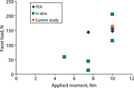
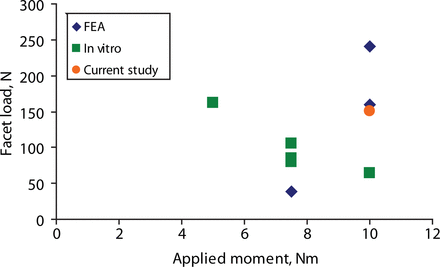
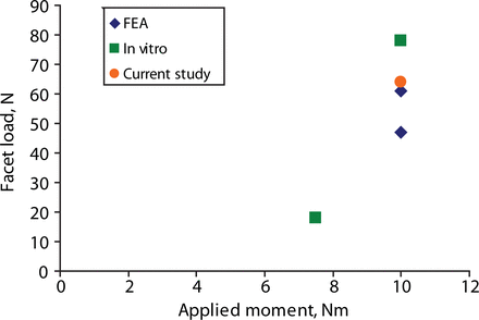
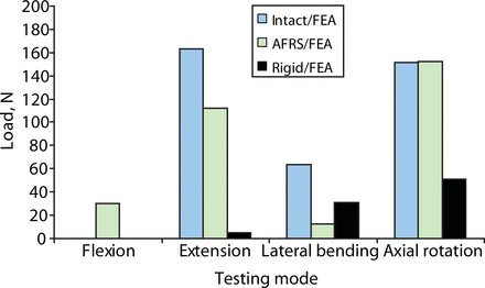
The predicted facet loads for the intact spine model were within the range of those reported in the literature (Table 3, Figures 8–10). The implant facet loads predicted by the model were very close to the intact values in extension and axial rotation (Figure 11). In flexion, a minimal facet load of 30 N was found with the device. The facet loads for the rigid fixation system model were very small in comparison.
Reported extension facet loads for finite element analysis (FEA), in vitro, and our study.
Reported axial rotation facet loads for finite element analysis (FEA), in vitro, and our study.
Reported lateral bending facet loads for finite element analysis (FEA), in vitro, and our study.
Predicted loads in facets across the implanted level (L4-L5) from finite element analysis (FEA): intact, Anatomic Facet Replacement System (AFRS)–repaired, and rigid models.
Predicted Facet Loads Compared With Values From the Literature
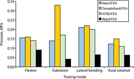
Finite element study predicted that the intradiscal pressures across the destabilized level increased substantially from intact values, especially in extension (a 136% increase). The artificial facet system was able to reduce the intradiscal pressure back to the intact values (Figure 12) in all the modes. By contrast, with the rigid system, the pressure across the implanted level was up to 71% less than intact values in extension.
Predicted intradiscal pressure across the implanted level (L4-L5) from finite element analysis (FEA): intact, destabilized, Anatomic Facet Replacement System (AFRS)–repaired, and rigid models.
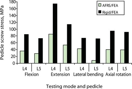
The peak pedicle-to-bone interface stress in the facet replacement implant was 85 MPa in extension compared with 174 MPa in the rigid system (Figure 13). These values are small compared with a yield stress of 827 MPa for cobalt-chromium28, 29 and 795 MPa for titanium.30 The screws are titanium, which has a yield strength of 795 MPa. The maximum contact stress between the opposing artificial facets was 69 MPa in extension.
Predicted pedicle screw stress at the screw-bone interface from finite element analysis (FEA): Anatomic Facet Replacement System (AFRS)–repaired and rigid models.
DISCUSSION
The range-of-motion data from the cadaveric study elucidated the kinematics of the lumbar spine while enabling us to assess the motion predictions of the finite element model. The primary purpose of using the experimentally validated model was to make predictions regarding facet and implant loading and intradiscal pressures. Reliable data for these parameters can be challenging to obtain experimentally.31, 32 For example, the in vitro (experimental studies)–based facet loads show a wide variation (from 3% to 20%) for several reasons: expected variations in the experimental studies, variations in the facet orientation from specimen to specimen, limitations of the transducer technology used for pressure measurements (e.g., Tekscan vs Fuji film), the ability to accurately calibrate the sensors, and, finally, placement of the transducer itself within the opposing facets (Table 3 and Figures 8–10). Conversely, it is difficult for the finite element model to account for the anatomic variability present in the population.33, 34 Hence, employing both a theoretical and an experimental approach allows for a more complete investigation of this complex system.
Predicted model and experimental values agree reasonably well for range of motion. Both cadaveric and finite element results showed that the facet replacement implant was able to restore stability after destabilization. Finite element analysis also showed near-equal facet loads with the facet replacement device compared to natural joint loads in extension and axial rotation. The model predicted that intradiscal pressure with the facet replacement device would be very close to the intact values in all the modes of motion and much larger for the destabilized condition. The close agreement of motion and intradiscal pressures across the artificial facet system implanted level with the intact indicates that the device may prevent adjacent level degeneration.
Hybrid protocol is essential to highlight the adjacent level effects following “stabilization,” where the implant makes the segment too rigid (e.g., a rigid fixation system) or too flexible (e.g., a dynamic system). The increase in adjacent level loads and intradiscal pressures with the rigid system have been highlighted in other studies by means of hybrid protocol.35 However, our data clearly show that motion at the implanted level is very close to the normal and, thus, there is no need to undertake a hybrid protocol testing for this investigation.
Although the rigid fixation system led to increased stability in the finite element model, the predicted screw stresses at the bone-pedicle screw interface were much larger than those of the facet replacement system. Pedicle screw loosening has been a well documented failure mode for rigid fixation systems.36 The reduction in pedicle screw stress may afford the facet replacement system better long term fatigue performance. The facet implant's anatomic design most likely contributed to its ability to replicate natural mechanics. However, facet loads and segment mechanics may change somewhat with change in the orientation of the artificial facets. We are currently pursuing additional parametric biomechanical studies to investigate the impact of these variations. Long-term clinical outcome data are needed to determine the true performance of artificial facet systems such as the AFRS.
Footnotes
The authors declare no conflict of interest.
Institutional review board approval was not required for this study.
- Received January 3, 2007.
- Accepted February 21, 2007.
- Copyright SAS - Spine Arthroplasty Society 2007
This is an Open Access article distributed under the terms of the Creative Commons Attribution-Noncommercial 3.0 Unported License, permitting all non-commercial use, distribution, and reproduction in any medium, provided the original work is properly cited.


